Difference: MassStorage (1 vs. 23)
Revision 232019-05-30 - PeterSchmid
| Line: 1 to 1 | ||||||||
|---|---|---|---|---|---|---|---|---|
%DASHBOARD{ section="banner" | ||||||||
| Line: 316 to 316 | ||||||||
| Changed: | ||||||||
| < < | For RAM only Membership Cards you need some kind of bootstrap loader. To type in a monitor or even BASIC or FORTH is nearly impossible. Serial EEPROMs in DIP8 packages are cheap and easy to get. But you still have to use the front panel to type in the boot loader itself (this is the first-stage boot loader). | |||||||
| > > | For RAM only Membership Cards you need some kind of bootstrap loader. To toggle in a monitor or even BASIC or FORTH is nearly impossible. Serial EEPROMs in DIP8 packages are cheap and easy to get. But you still have to use the front panel to toggle in the boot loader itself (this is the first-stage boot loader). | |||||||
|
The "patched on MC PCB" boot loader takes about 25 s for 32 KiB, the DB25 variant takes about 29 s. For the sources see https://github.com/spyren/RaspiElf/tree/master/eeprom | ||||||||
Revision 222019-02-10 - PeterSchmid
| Line: 1 to 1 | ||||||||
|---|---|---|---|---|---|---|---|---|
%DASHBOARD{ section="banner" | ||||||||
| Line: 15 to 15 | ||||||||
| Changed: | ||||||||
| < < | The Serial Peripheral Interface SPI | |||||||
| > > | The Serial Peripheral Interface SPI | |||||||
CLK MC ->- host MOSI MC ->- host | ||||||||
| Line: 26 to 26 | ||||||||
| A high-to-low transition on the CS pin is required to start an operation and a low-to-high transition is required to end an operation. | ||||||||
| Changed: | ||||||||
| < < | Invalid Opcode: If an invalid opcode is received, no data will be shifted into AT25M02 and the Serial Data | |||||||
| > > | Invalid Opcode: If an invalid opcode is received, no data will be shifted into AT25M02 and the Serial Data | |||||||
| Output (SO) pin will remain in a high impedance state until the falling edge of CS is detected again. This will reinitialize the serial communication. | ||||||||
Revision 212019-02-10 - PeterSchmid
| Line: 1 to 1 | ||||||||
|---|---|---|---|---|---|---|---|---|
%DASHBOARD{ section="banner" | ||||||||
| Line: 15 to 15 | ||||||||
| Changed: | ||||||||
| < < | The Serial Peripheral Interface SPI | |||||||
| > > | The Serial Peripheral Interface SPI | |||||||
CLK MC ->- host MOSI MC ->- host | ||||||||
| Line: 110 to 110 | ||||||||
| Changed: | ||||||||
| < < | about 230 cycles for one byte -> 1 ms -> 1 KiB takes about 1 s @ 1.79 MHz | |||||||
| > > | about 230 cycles for one byte -> 1 ms -> 1 KiB takes about 1 s @ 1.79 MHz | |||||||
Write Byte | ||||||||
| Line: 179 to 179 | ||||||||
| BNZ RDBITLOOP | ||||||||
| Changed: | ||||||||
| < < | about 200 cycles for one byte -> 1 ms -> 1 KiB takes about 1 s | |||||||
| > > | about 200 cycles for one byte -> 1 ms -> 1 KiB takes about 1 s | |||||||
Write Byte | ||||||||
| Line: 205 to 205 | ||||||||
| Added: | ||||||||
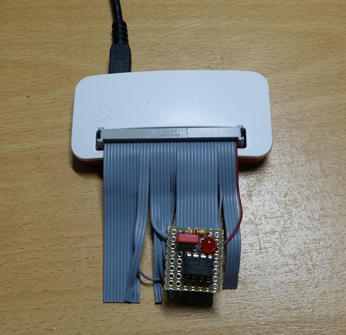
| > > | I use a Raspberry Pi Zero (about $20) as an EEPROM programmer. | |||||||
| Line: 316 to 318 | ||||||||
Mini Boot LoaderFor RAM only Membership Cards you need some kind of bootstrap loader. To type in a monitor or even BASIC or FORTH is nearly impossible. Serial EEPROMs in DIP8 packages are cheap and easy to get. But you still have to use the front panel to type in the boot loader itself (this is the first-stage boot loader). | ||||||||
| Changed: | ||||||||
| < < | The "patched on MC PCB" boot loader takes about 25 s for 32 KiB, the DB25 variant takes about 29 s. For the sources see https://github.com/spyren/RaspiElf/tree/master/eeprom | |||||||
| > > | The "patched on MC PCB" boot loader takes about 25 s for 32 KiB, the DB25 variant takes about 29 s. For the sources see https://github.com/spyren/RaspiElf/tree/master/eeprom | |||||||
|
| ||||||||
Revision 202019-02-09 - PeterSchmid
| Line: 1 to 1 | ||||||||
|---|---|---|---|---|---|---|---|---|
%DASHBOARD{ section="banner" | ||||||||
| Line: 62 to 62 | ||||||||
| ||||||||
| Changed: | ||||||||
| < < | ||||||||
| > > | ||||||||
| Sharing the LED and Switch port, you loose three LEDs and one switch or IN. Possible conflict with the bootstrap loader, if there is a read sequence (CS and read pattern 0000 0011). To prevent this, set the EEPROM into HOLD state e.g. with the WAIT signal. | ||||||||
| Line: 78 to 78 | ||||||||
| ||||||||
| Changed: | ||||||||
| < < |  | |||||||
| > > |
| |||||||
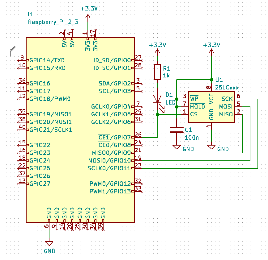
| Raspberry Pi can emulate SPI EEPROM. On RaspiElf the switches/LEDs are already connected to Raspi's GPIOs. No need for additional hardware. But I have to write an SPI server for the Raspberry Pi. Raspi's SPI interfaces can't be used because of conflicting port usage. | ||||||||
| Line: 86 to 87 | ||||||||
Read Byte | ||||||||
| Changed: | ||||||||
| < < | CS0 EQU 0b1101111 CS1 EQU 0b0010000 CLK0 EQU 0b1011111 CLK1 EQU 0b0100000 DATA0 EQU 0b0111111 DATA1 EQU 0b1000000 ; MSB first READBYTE: LDI 0 PLO R5 LDI 0xFF PHI R6 LDI 0xFF - 8 PLO R6 SEX R0 BITLOOP: INC R6 GHI R6 ; set CARRY SHRC GLO R5 B4 SETBIT ; branch if bit set | |||||||
| > > | LDI 01H PLO R4 ; for the carry PLO R5 ; reset all bits LDI 8 ; counting down 8 times PLO R6 ; bit counter RDBITLOOP GLO R4 ; set CARRY SHR GLO R5 ; get bits BN4 SETBIT ; branch if bit set (EF4 == 0) | |||||||
| SHL ; bit not set | ||||||||
| Changed: | ||||||||
| < < | SKP SETBIT: SHLC SAVEBIT: PLO R5 OUT4 BYTE 0b01000000 ; CLK for SPI OUT4 BYTE 0b00000000 | |||||||
| > > | SKP ; BR SAVEBIT SETBIT SHLC ; set bit SAVEBIT OUT P4 ; CLK on for SPI BYTE 01000000B OUT P4 ; CLK off BYTE 00000000b PLO R5 ; save bits DEC R6 | |||||||
| GLO R6 | ||||||||
| Changed: | ||||||||
| < < | BNZ BITLOOP | |||||||
| > > | BNZ RDBITLOOP | |||||||
about 230 cycles for one byte -> 1 ms -> 1 KiB takes about 1 s @ 1.79 MHz
Write Byte | ||||||||
| Changed: | ||||||||
| < < | WRITEBYTE: LDI 0 PHI R6 LDI 8 | |||||||
| > > | WRITEBYTE PLO R5 ; save transmit byte LDI 8 ; counter 8 bits | |||||||
| PLO R6 | ||||||||
| Changed: | ||||||||
| < < | SEX R0 BITLOOP: GLO R5 ; get the next bit SHLC , next bit is in the carry | |||||||
| > > | WRBITLOOP GLO R5 ; get the next bit SHL ; next bit is in the carry | |||||||
| PLO R5 | ||||||||
| Changed: | ||||||||
| < < | BDF SETBIT OUT P4 BYTE 0b01000000 ; CLK for SPI with data bit cleared OUT P4 BYTE 0b00000000 BR NEXT SETBIT: OUT P4 BYTE 0b11000000 ; CLK for SPI with data bit set OUT P4 BYTE 0b10000000 NEXT: DEC R6 | |||||||
| > > | BDF BITSET OUT P4 ; bit cleared BYTE 00000000B OUT P4 ; clock on BYTE 01000000B OUT P4 ; clock off BYTE 00000000B BR WRTEST BITSET OUT P4 ; bit set BYTE 10000000B OUT P4 ; clock on BYTE 11000000B OUT P4 ; clock off BYTE 10000000B WRTEST DEC R6 | |||||||
| GLO R6 | ||||||||
| Changed: | ||||||||
| < < | BNZ BITLOOP | |||||||
| > > | ||||||||
|
EEPROM patched on MC PCB
| ||||||||
| Line: 331 to 315 | ||||||||
Mini Boot Loader
Mini Boot LoaderFor RAM only Membership Cards you need some kind of bootstrap loader. To type in a monitor or even BASIC or FORTH is nearly impossible. Serial EEPROMs in DIP8 packages are cheap and easy to get. But you still have to use the front panel to type in the boot loader itself (this is the first-stage boot loader). | ||||||||
| Added: | ||||||||
| > > |
The "patched on MC PCB" boot loader takes about 25 s for 32 KiB, the DB25 variant takes about 29 s. For the sources see https://github.com/spyren/RaspiElf/tree/master/eeprom | |||||||
                        ;       TITL    "EEPROM Boot Loader for Elf Memebership Card"
                        ;               EJCT    60
| ||||||||
| Line: 523 to 511 | ||||||||
| ||||||||
| Added: | ||||||||
| > > |
| |||||||


Revision 192019-02-09 - PeterSchmid
| Line: 1 to 1 | ||||||||
|---|---|---|---|---|---|---|---|---|
%DASHBOARD{ section="banner" | ||||||||
| Line: 248 to 248 | ||||||||
| ||||||||
| Changed: | ||||||||
| < < |
| |||||||
| > > |
| |||||||
| ||||||||
| Line: 264 to 264 | ||||||||
| ||||||||
| Added: | ||||||||
| > > |
| |||||||
bin2eeprom (upload tool)
| ||||||||
| Changed: | ||||||||
| < < |
| |||||||
| > > |
| |||||||
| ||||||||
| Line: 285 to 286 | ||||||||
| ||||||||
| Added: | ||||||||
| > > |
| |||||||
How to get and build the EEPROM tools | ||||||||
Revision 182019-02-09 - PeterSchmid
| Line: 1 to 1 | ||||||||||||||||||||||
|---|---|---|---|---|---|---|---|---|---|---|---|---|---|---|---|---|---|---|---|---|---|---|
%DASHBOARD{ section="banner" | ||||||||||||||||||||||
| Line: 35 to 35 | ||||||||||||||||||||||
| From 1024 Kibit up there are 24 address bits, 8 Kibit to 512 Kibit have 16 address bits. 1, 2, and 4 Kibit have 8 bit address bits. | ||||||||||||||||||||||
| Added: | ||||||||||||||||||||||
| > > | SPI Serial EEPROM Family Data Sheet 25AAXXXX/25LCXXXX | |||||||||||||||||||||
25LCxxxx Instruction Set
| ||||||||||||||||||||||
| Line: 246 to 248 | ||||||||||||||||||||||
| ||||||||||||||||||||||
| Changed: | ||||||||||||||||||||||
| < < |
| |||||||||||||||||||||
| > > |
| |||||||||||||||||||||
| Changed: | ||||||||||||||||||||||
| < < |
| |||||||||||||||||||||
| > > |
| |||||||||||||||||||||
| ||||||||||||||||||||||
| Added: | ||||||||||||||||||||||
| > > |
| |||||||||||||||||||||
bin2eeprom (upload tool)
| ||||||||||||||||||||||
| Changed: | ||||||||||||||||||||||
| < < |
| |||||||||||||||||||||
| > > |
| |||||||||||||||||||||
| Changed: | ||||||||||||||||||||||
| < < |
| |||||||||||||||||||||
| > > |
| |||||||||||||||||||||
| ||||||||||||||||||||||
| Added: | ||||||||||||||||||||||
| > > |
| |||||||||||||||||||||
How to get and build the EEPROM tools | ||||||||||||||||||||||
Revision 172019-02-06 - PeterSchmid


Revision 162019-02-06 - PeterSchmid
| Line: 1 to 1 | ||||||||
|---|---|---|---|---|---|---|---|---|
%DASHBOARD{ section="banner" | ||||||||
| Line: 103 to 103 | ||||||||
| PLO R6 SEX R0 BITLOOP: | ||||||||
| Deleted: | ||||||||
| < < | OUT4,0b01000000 ; CLK for SPI OUT4,0b00000000 | |||||||
| INC R6 GHI R6 ; set CARRY SHRC GLO R5 B4 SETBIT ; branch if bit set SHL ; bit not set | ||||||||
| Changed: | ||||||||
| < < | BR SAVEBIT | |||||||
| > > | SKP | |||||||
| SETBIT: SHLC SAVEBIT: PLO R5 | ||||||||
| Added: | ||||||||
| > > | OUT4 BYTE 0b01000000 ; CLK for SPI OUT4 BYTE 0b00000000 | |||||||
| GLO R6 BNZ BITLOOP | ||||||||
| Line: 135 to 137 | ||||||||
| SHLC , next bit is in the carry PLO R5 BDF SETBIT | ||||||||
| Changed: | ||||||||
| < < | OUT4,0b01000000 ; CLK for SPI with data bit cleared OUT4,0b00000000 | |||||||
| > > | OUT P4 BYTE 0b01000000 ; CLK for SPI with data bit cleared OUT P4 BYTE 0b00000000 | |||||||
| BR NEXT SETBIT: | ||||||||
| Changed: | ||||||||
| < < | OUT4,0b11000000 ; CLK for SPI with data bit set OUT4,0b10000000 | |||||||
| > > | OUT P4 BYTE 0b11000000 ; CLK for SPI with data bit set OUT P4 BYTE 0b10000000 | |||||||
| NEXT: DEC R6 GLO R6 | ||||||||
Revision 152019-02-06 - PeterSchmid
| Line: 1 to 1 | ||||||||
|---|---|---|---|---|---|---|---|---|
%DASHBOARD{ section="banner" | ||||||||
| Line: 168 to 168 | ||||||||
Read Byte | ||||||||
| Added: | ||||||||
| > > | LDI 01 PLO R4 ; for the carry | |||||||
| GHI R0 ; D = 0 PLO R5 ; reset all bits LDI 0 - 8 ; counting up 8 times | ||||||||
| Line: 177 to 179 | ||||||||
| GLO R5 BN2 SETBIT ; branch if bit set (EF2 == 0) SHL ; bit not set | ||||||||
| Changed: | ||||||||
| < < | BR SAVEBIT | |||||||
| > > | SKP ; BR SAVEBIT | |||||||
| SETBIT SHLC SAVEBIT OUT P2 ; CLK for SPI, INC Rx PLO R5 | ||||||||
Revision 142019-02-05 - PeterSchmid
| Line: 1 to 1 | ||||||||
|---|---|---|---|---|---|---|---|---|
%DASHBOARD{ section="banner" | ||||||||
| Line: 168 to 168 | ||||||||
Read Byte | ||||||||
| Changed: | ||||||||
| < < | ; MSB first LDI 0 PLO R5 LDI 0xFF PHI R6 LDI 0xFF - 8 PLO R6 SEX R6 BITLOOP: OUT2 ; CLK for SPI, INC Rx GHI R6 ; set CARRY SHRC | |||||||
| > > | GHI R0 ; D = 0 PLO R5 ; reset all bits LDI 0 - 8 ; counting up 8 times PLO R6 ; bit counter RDBITLOOP GLO R4 ; set CARRY SHR | |||||||
| GLO R5 | ||||||||
| Changed: | ||||||||
| < < | B2 SETBIT ; branch if bit set | |||||||
| > > | BN2 SETBIT ; branch if bit set (EF2 == 0) | |||||||
| SHL ; bit not set BR SAVEBIT | ||||||||
| Changed: | ||||||||
| < < | SETBIT: SHLC SAVEBIT: | |||||||
| > > | SETBIT SHLC SAVEBIT OUT P2 ; CLK for SPI, INC Rx | |||||||
| PLO R5 GLO R6 | ||||||||
| Changed: | ||||||||
| < < | BNZ BITLOOP | |||||||
| > > | BNZ RDBITLOOP | |||||||
| about 200 cycles for one byte -> 1 ms -> 1 KiB takes about 1 s | ||||||||
| Line: 198 to 190 | ||||||||
Write Byte | ||||||||
| Changed: | ||||||||
| < < | WRITEBYTE: LDI 0 PHI R6 LDI 8 | |||||||
| > > | WRITEBYTE PLO R5 ; save transmit byte LDI 8 ; counter 8 bits | |||||||
| PLO R6 | ||||||||
| Changed: | ||||||||
| < < | SEX R0 BITLOOP: GLO R5 ; get the next bit SHLC , next bit is in the carry | |||||||
| > > | WRBITLOOP GLO R5 ; get the next bit SHL ; next bit is in the carry | |||||||
| PLO R5 | ||||||||
| Changed: | ||||||||
| < < | LSNF OUT2,0b00000000 ; CLK for SPI with data bit cleared LSDF OUT2,0b00000001 ; CLK for SPI with data bit set | |||||||
| > > | LSNF ; skip if bit is 0 OUT P2 BYTE 00000001B ; CLK for SPI with data bit cleared LSDF ; skip if bit is 1 OUT P2 BYTE 00000000B ; CLK for SPI with data bit set | |||||||
| DEC R6 GLO R6 | ||||||||
| Changed: | ||||||||
| < < | BNZ BITLOOP | |||||||
| > > | BNZ WRBITLOOP | |||||||
| Line: 311 to 301 | ||||||||
| Changed: | ||||||||
| < < | ; MSB first LDI xyz ; EEPROM read command PLO R9 LDI 0 PLO R7 ; set page pointer PHI R8 ; set EEPROM address PLO R8 LDI 0x80 PHI R7 ; set block pointer BLOCKLOOP: GLO R9 ; write read command to the EEPROM PLO R5 CALL WRITEBYTE LDI 0 ; address bit 17 to 24 PLO R5 CALL WRITEBYTE GHI R8 ; address bit 8 to 16 PLO R5 CALL WRITEBYTE GLO R8 ; address bit 8 to 16 PLO R5 PAGELOOP: LDI 0 ; init read byte PLO R5 LDI 0xFF ; for the carry bits PHI R6 LDI 0xFF - 8 ; counting up 8 times PLO R6 ; bit counter SEX R6 ; dummy Rx for OUT RDBITLOOP: OUT2 ; CLK for SPI, INC Rx GHI R6 ; set CARRY SHRC GLO R5 B2 SETBIT ; branch if bit set SHL ; bit not set BR SAVEBIT SETBIT: SHLC SAVEBIT: PLO R5 GLO R6 BNZ BITLOOP GLO R5 ; get byte | |||||||
| > > | ; TITL "EEPROM Boot Loader for Elf Memebership Card" ; EJCT 60 | |||||||
| Added: | ||||||||
| > > | CPU 1802 | |||||||
| Changed: | ||||||||
| < < | WRITEBYTE: LDI 0 PHI R6 LDI 8 PLO R6 SEX R0 WRBITLOOP: GLO R5 ; get the next bit SHLC , next bit is in the carry PLO R5 LSNF OUT2,0b00000000 ; CLK for SPI with data bit cleared LSDF OUT2,0b00000001 ; CLK for SPI with data bit set DEC R6 GLO R6 BNZ BITLOOP | |||||||
| > > | NUMBER EQU 0 | |||||||
| Added: | ||||||||
| > > | ;
; Register Definitions:
;
R0 EQU 0
R1 EQU 1
R2 EQU 2
R3 EQU 3
R4 EQU 4
R5 EQU 5
R6 EQU 6
R7 EQU 7
R8 EQU 8
R9 EQU 9
R10 EQU 10
R11 EQU 11
R12 EQU 12
R13 EQU 13
R14 EQU 14
R15 EQU 15
;
; I/O Port Definitions:
;
P1 EQU 1
P2 EQU 2
P3 EQU 3
P4 EQU 4
P5 EQU 5
P6 EQU 6
P7 EQU 7
ORG 0H
; R0 program counter
; R1 subroutine pc
; R2 stack pointer
; R5.0 byte (read/write)
; R6.0 bit counter
; R4.0 carry bits
; R7 destination address
; R8 length
BOOTLOADER
| |||||||
| Added: | ||||||||
| > > | END | |||||||
Revision 132019-02-02 - PeterSchmid
| Line: 1 to 1 | |||||||||||||||||
|---|---|---|---|---|---|---|---|---|---|---|---|---|---|---|---|---|---|
%DASHBOARD{ section="banner" | |||||||||||||||||
| Line: 150 to 150 | |||||||||||||||||
| Changed: | |||||||||||||||||
| < < | SPI Mode 0, data is always latched in on the rising edge of SCK and always output on the falling edge of SCK. For CS one output port bis is needed e.g. O7 or N2 (INP4) to start/end operation (A high-to-low transition on the CS pin is required to start an operation and a low-to-high transition is required to end an operation). | ||||||||||||||||
| > > | SPI Mode 0, data is always latched in on the rising edge of SCK and always output on the falling edge of SCK. For CS one output port bis is needed e.g. O7 or N0 (INP1) to start/end operation (A high-to-low transition on the CS pin is required to start an operation and a low-to-high transition is required to end an operation). | ||||||||||||||||
| |||||||||||||||||
| Changed: | |||||||||||||||||
| < < |
| ||||||||||||||||
| > > |
| ||||||||||||||||
| |||||||||||||||||
Revision 122019-02-01 - PeterSchmid
| Line: 1 to 1 | ||||||||
|---|---|---|---|---|---|---|---|---|
%DASHBOARD{ section="banner" | ||||||||
| Line: 307 to 307 | ||||||||
| Added: | ||||||||
| > > | Mini Boot Loader
Mini Boot Loader
        ; MSB first

        LDI     xyz          ; EEPROM read command
        PLO     R9
        LDI     0
        PLO     R7           ; set page pointer
        PHI     R8           ; set EEPROM address
        PLO     R8
        LDI     0x80
        PHI     R7           ; set block pointer
BLOCKLOOP:

        GLO     R9           ; write read command to the EEPROM
        PLO     R5
        CALL    WRITEBYTE
        LDI     0            ; address bit 17 to 24
        PLO     R5
        CALL    WRITEBYTE
        GHI     R8           ; address bit 8 to 16
        PLO     R5
        CALL    WRITEBYTE
        GLO     R8           ; address bit 8 to 16
        PLO     R5

PAGELOOP:
        LDI     0            ; init read byte
        PLO     R5
        LDI     0xFF         ; for the carry bits
        PHI     R6
        LDI     0xFF - 8     ; counting up 8 times
        PLO     R6           ; bit counter
        SEX     R6           ; dummy Rx for OUT
RDBITLOOP:
        OUT2                 ; CLK for SPI, INC Rx
        GHI     R6           ; set CARRY
        SHRC
        GLO     R5
        B2      SETBIT       ; branch if bit set
        SHL                  ; bit not set
        BR      SAVEBIT
SETBIT:
        SHLC
SAVEBIT:
        PLO     R5
        GLO     R6
        BNZ     BITLOOP
        GLO     R5           ; get byte


WRITEBYTE:
        LDI     0
        PHI     R6
        LDI     8
        PLO     R6
        SEX     R0
WRBITLOOP:
        GLO     R5           ; get the next bit
        SHLC                 , next bit is in the carry
        PLO     R5
        LSNF
        OUT2,0b00000000      ; CLK for SPI with data bit cleared
        LSDF
        OUT2,0b00000001      ; CLK for SPI with data bit set
        DEC     R6
        GLO     R6
        BNZ     BITLOOP
| |||||||
Revision 112019-01-29 - PeterSchmid
| Line: 1 to 1 | ||||||||
|---|---|---|---|---|---|---|---|---|
%DASHBOARD{ section="banner" | ||||||||
| Line: 320 to 320 | ||||||||
| Added: | ||||||||
| > > | ||||||||
Revision 102019-01-28 - PeterSchmid
| Line: 1 to 1 | ||||||||
|---|---|---|---|---|---|---|---|---|
%DASHBOARD{ section="banner" | ||||||||
| Line: 268 to 268 | ||||||||
| ||||||||
| Changed: | ||||||||
| < < | How to get and build the RaspiElf tools | |||||||
| > > | How to get and build the EEPROM tools | |||||||
Get the source from the GIT repositorysudo apt-get install git), type only the bold text after the $ sign: | ||||||||
| Line: 281 to 281 | ||||||||
Build (compile) from the sources:
pi@cosmac:~/elf $ cd RaspiElf | ||||||||
| Changed: | ||||||||
| < < | pi@cosmac:~/elf/RaspiElf $ cd eeprom/ | |||||||
| > > | pi@cosmac:~/elf/RaspiElf $ cd eeprom | |||||||
| pi@cosmac:~/elf/RaspiElf/eeprom $ make cc -g -c eeprom2bin.c cc -g -o eeprom2bin -lwiringPi eeprom2bin.o | ||||||||
Revision 92019-01-28 - PeterSchmid
| Line: 1 to 1 | ||||||||
|---|---|---|---|---|---|---|---|---|
%DASHBOARD{ section="banner" | ||||||||
| Line: 318 to 318 | ||||||||
| https://github.com/utoh/pygmy-forth/blob/master/extras/kermit/pfkerm.doc | ||||||||
| Added: | ||||||||
| > > | ||||||||
Revision 82019-01-28 - PeterSchmid
| Line: 1 to 1 | ||||||||
|---|---|---|---|---|---|---|---|---|
%DASHBOARD{ section="banner" | ||||||||
| Line: 15 to 15 | ||||||||
| Changed: | ||||||||
| < < | The Serial Peripheral Interface SPI | |||||||
| > > | The Serial Peripheral Interface SPI | |||||||
CLK MC ->- host MOSI MC ->- host | ||||||||
Revision 72019-01-27 - PeterSchmid
| Line: 1 to 1 | ||||||||
|---|---|---|---|---|---|---|---|---|
%DASHBOARD{ section="banner" | ||||||||
| Line: 182 to 182 | ||||||||
| SHRC GLO R5 B2 SETBIT ; branch if bit set | ||||||||
| Changed: | ||||||||
| < < | SHR ; bit not set | |||||||
| > > | SHL ; bit not set | |||||||
| BR SAVEBIT SETBIT: | ||||||||
| Changed: | ||||||||
| < < | SHRC | |||||||
| > > | SHLC | |||||||
| SAVEBIT: PLO R5 GLO R6 | ||||||||
| Line: 239 to 239 | ||||||||
| ||||||||
| Changed: | ||||||||
| < < |  | |||||||
| > > |
| |||||||
| Deleted: | ||||||||
| < < | Because of: "A high-to-low transition on the CS pin is required to start an operation and a low-to-high transition is required to end an operation." That means the CS has to be active as long as a read or write process is going on. Therefore the SPI0 CSx can't be used. | |||||||
eeprom2bin (download tool) | ||||||||
| Line: 268 to 268 | ||||||||
| ||||||||
| Added: | ||||||||
| > > | How to get and build the RaspiElf toolsGet the source from the GIT repositorysudo apt-get install git), type only the bold text after the $ sign:
pi@cosmac:~/elf $ git clone https://github.com/spyren/RaspiElf
Cloning into 'RaspiElf'...
pi@cosmac:~/elf $
Build (compile) from the sources: pi@cosmac:~/elf $ cd RaspiElf pi@cosmac:~/elf/RaspiElf $ cd eeprom/ pi@cosmac:~/elf/RaspiElf/eeprom $ make cc -g -c eeprom2bin.c cc -g -o eeprom2bin -lwiringPi eeprom2bin.o cc -g -c bin2eeprom.c cc -g -o bin2eeprom -lwiringPi bin2eeprom.o pi@cosmac:~/elf/RaspiElf/eeprom $Install the binaries into /usr/local/bin
pi@cosmac:~/elf/RaspiElf/eeprom $ sudo make install
install -m 557 eeprom2bin bin2eeprom /usr/local/bin
Install wiringPi (GPIO Interface library for the Raspberry Pi), details see http://wiringpi.com/download-and-install/ @cosmac:~/elf/RaspiElf/eeprom $ sudo raspi-config
| |||||||
| Line: 290 to 328 | ||||||||
| Changed: | ||||||||
| < < |
| |||||||
| > > |
| |||||||
Revision 62019-01-27 - PeterSchmid
| Line: 1 to 1 | ||||||||
|---|---|---|---|---|---|---|---|---|
%DASHBOARD{ section="banner" | ||||||||
| Line: 217 to 217 | ||||||||
| Changed: | ||||||||
| < < | SEEPROM Connected to Raspberry Pi
| |||||||
| > > | EEPROM Connected to Raspberry Pi
| |||||||
EEPROM Connected to Raspberry Pi | ||||||||
Revision 52019-01-26 - PeterSchmid
| Line: 1 to 1 | ||||||||
|---|---|---|---|---|---|---|---|---|
%DASHBOARD{ section="banner" | ||||||||
| Line: 60 to 60 | ||||||||
| ||||||||
| Changed: | ||||||||
| < < | ||||||||
| > > | ||||||||
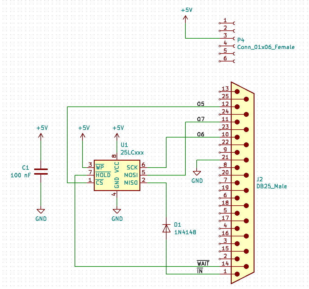
| Sharing the LED and Switch port, you loose three LEDs and one switch or IN. Possible conflict with the bootstrap loader, if there is a read sequence (CS and read pattern 0000 0011). To prevent this, set the EEPROM into HOLD state e.g. with the WAIT signal. | ||||||||
| Line: 147 to 147 | ||||||||
| BNZ BITLOOP | ||||||||
| Changed: | ||||||||
| < < | ||||||||
| > > | ||||||||
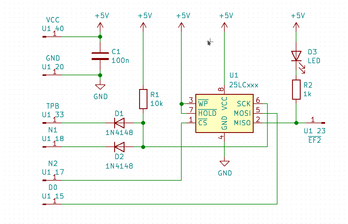
| SPI Mode 0, data is always latched in on the rising edge of SCK and always output on the falling edge of SCK. For CS one output port bis is needed e.g. O7 or N2 (INP4) to start/end operation (A high-to-low transition on the CS pin is required to start an operation and a low-to-high transition is required to end an operation). | ||||||||
| Line: 217 to 217 | ||||||||
| Changed: | ||||||||
| < < | ||||||||
| > > | ||||||||
Revision 42019-01-26 - PeterSchmid
| Line: 1 to 1 | ||||||||||
|---|---|---|---|---|---|---|---|---|---|---|
%DASHBOARD{ section="banner" | ||||||||||
| Line: 15 to 15 | ||||||||||
| Changed: | ||||||||||
| < < | The Serial Peripheral Interface SPI | |||||||||
| > > | The Serial Peripheral Interface SPI | |||||||||
CLK MC ->- host MOSI MC ->- host | ||||||||||
| Line: 33 to 33 | ||||||||||
| While in Hold mode, the SO pin will be in a high impedance state. In addition, both the SI pin and the SCK pin will be ignored. | ||||||||||
| Added: | ||||||||||
| > > | From 1024 Kibit up there are 24 address bits, 8 Kibit to 512 Kibit have 16 address bits. 1, 2, and 4 Kibit have 8 bit address bits. | |||||||||
25LCxxxx Instruction Set
| ||||||||||
| Line: 218 to 220 | ||||||||||
| Changed: | ||||||||||
| < < | http://www.netzmafia.de/skripten/hardware/RasPi/RasPi_SPI.html | |||||||||
| > > | ||||||||||
| ||||||||||
| Changed: | ||||||||||
| < < |
| |||||||||
| > > |
| |||||||||
| ||||||||||
| Changed: | ||||||||||
| < < |
| |||||||||
| > > |
| |||||||||
| ||||||||||
| Line: 234 to 239 | ||||||||||
| ||||||||||
| Changed: | ||||||||||
| < < |  | |||||||||
| > > | | |||||||||
| Changed: | ||||||||||
| < < | Read Byte | |||||||||
| > > | Because of: "A high-to-low transition on the CS pin is required to start an operation and a low-to-high transition is required to end an operation." That means the CS has to be active as long as a read or write process is going on. Therefore the SPI0 CSx can't be used.
eeprom2bin (download tool)
bin2eeprom (upload tool)
| |||||||||
| Deleted: | ||||||||||
| < < | Write Byte | |||||||||
|
Kermit/ZModem
| ||||||||||
| Line: 261 to 289 | ||||||||||
Comments\ No newline at end of file | ||||||||||
| Added: | ||||||||||
| > > |
| |||||||||
Revision 32019-01-26 - PeterSchmid
| Line: 1 to 1 | ||||||||||
|---|---|---|---|---|---|---|---|---|---|---|
%DASHBOARD{ section="banner" | ||||||||||
| Line: 225 to 225 | ||||||||||
| ||||||||||
| Changed: | ||||||||||
| < < |
| |||||||||
| > > |
| |||||||||
| ||||||||||
Revision 22019-01-26 - PeterSchmid
| Line: 1 to 1 | ||||||||||||||||||||||||||||||||||
|---|---|---|---|---|---|---|---|---|---|---|---|---|---|---|---|---|---|---|---|---|---|---|---|---|---|---|---|---|---|---|---|---|---|---|
%DASHBOARD{ section="banner"
image="/twiki/pub/Cosmac/RaspiElf/raspi-elfmemcard-s.jpg" | ||||||||||||||||||||||||||||||||||
| Changed: | ||||||||||||||||||||||||||||||||||
| < < | title="A Serial EEPROM as Mass Storage" | |||||||||||||||||||||||||||||||||
| > > | title="Serial EEPROMs as Mass Storage" | |||||||||||||||||||||||||||||||||
| titlestyle="color:#F00000;"
}%
Intro
| ||||||||||||||||||||||||||||||||||
| Changed: | ||||||||||||||||||||||||||||||||||
| < < | Forth without mass storage (blocks, screens) is a not complete. A SD-Card interface could be a reasonable solution but it is an overkill for a small Forth system. Small serial EEPROMs are for my opinion more suitable. | |||||||||||||||||||||||||||||||||
| > > | Forth without mass storage (blocks, screens) is a not complete. A SD-Card interface | |||||||||||||||||||||||||||||||||
| Changed: | ||||||||||||||||||||||||||||||||||
| < < | EEPROM Serial Communication
| |||||||||||||||||||||||||||||||||
| > > | SPI EEPROMs
| |||||||||||||||||||||||||||||||||
SPI EEPROMs | ||||||||||||||||||||||||||||||||||
| Changed: | ||||||||||||||||||||||||||||||||||
| < < | Serial Peripheral Interface SPI, MC is the SPI master, the host is the slave.
e.g. AT25M02 | |||||||||||||||||||||||||||||||||
| > > | The Serial Peripheral Interface SPI | |||||||||||||||||||||||||||||||||
CLK MC ->- host MOSI MC ->- host | ||||||||||||||||||||||||||||||||||
| Line: 62 to 61 | ||||||||||||||||||||||||||||||||||
| Changed: | ||||||||||||||||||||||||||||||||||
| < < | Sharing the LED and Switch port, you loose two LEDs and one switch. Possible conflict with the bootstrap loader, if there is a read sequence (CS and read pattern 0000 0011). To prevent this, set the EEPROM into HOLD state e.g. with the WAIT signal. | |||||||||||||||||||||||||||||||||
| > > | Sharing the LED and Switch port, you loose three LEDs and one switch or IN. Possible conflict with the bootstrap loader, if there is a read sequence (CS and read pattern 0000 0011). To prevent this, set the EEPROM into HOLD state e.g. with the WAIT signal. | |||||||||||||||||||||||||||||||||
| ||||||||||||||||||||||||||||||||||
| Line: 77 to 76 | ||||||||||||||||||||||||||||||||||
|
| ||||||||||||||||||||||||||||||||||
| Changed: | ||||||||||||||||||||||||||||||||||
| < < | Raspberry Pi can emulate SPI EEPROM. On RaspiElf the switches/LEDs are already connected to Raspi's GPIOs. No need for additional hardware. But I have to write an SPI server for the Raspberry Pi.
Raspi's SPI interfaces can't be used because of conflicting port usage.
| |||||||||||||||||||||||||||||||||
| > > | Raspberry Pi can emulate SPI EEPROM. On RaspiElf the switches/LEDs are already connected to Raspi's GPIOs. No need for additional hardware. But I have to write an SPI server for the Raspberry Pi. Raspi's SPI interfaces can't be used because of conflicting port usage. | |||||||||||||||||||||||||||||||||
Read Byte | ||||||||||||||||||||||||||||||||||
| Line: 231 to 215 | ||||||||||||||||||||||||||||||||||
| Added: | ||||||||||||||||||||||||||||||||||
| > > | Serial EEPROM connected to Raspberry Pi
Serial EEPROM connected to Raspberry Pihttp://www.netzmafia.de/skripten/hardware/RasPi/RasPi_SPI.html
Read ByteWrite Byte | |||||||||||||||||||||||||||||||||
Revision 12019-01-24 - PeterSchmid
| Line: 1 to 1 | |||||||||||||||||||||||||||||||||||||||||||||||||||||||||||||||||||||||||||||||||||||||||||||||||||||||||||||||||||||||||||||||||||||||
|---|---|---|---|---|---|---|---|---|---|---|---|---|---|---|---|---|---|---|---|---|---|---|---|---|---|---|---|---|---|---|---|---|---|---|---|---|---|---|---|---|---|---|---|---|---|---|---|---|---|---|---|---|---|---|---|---|---|---|---|---|---|---|---|---|---|---|---|---|---|---|---|---|---|---|---|---|---|---|---|---|---|---|---|---|---|---|---|---|---|---|---|---|---|---|---|---|---|---|---|---|---|---|---|---|---|---|---|---|---|---|---|---|---|---|---|---|---|---|---|---|---|---|---|---|---|---|---|---|---|---|---|---|---|---|---|
| Added: | |||||||||||||||||||||||||||||||||||||||||||||||||||||||||||||||||||||||||||||||||||||||||||||||||||||||||||||||||||||||||||||||||||||||
| > > |
A Serial EEPROM as Mass Storage
Intro
Forth without mass storage (blocks, screens) is a not complete. A SD-Card interface could be a reasonable solution but it is an overkill for a small Forth system. Small serial EEPROMs are for my opinion more suitable.
EEPROM Serial Communication
SPI EEPROMsSerial Peripheral Interface SPI, MC is the SPI master, the host is the slave. e.g. AT25M02CLK MC ->- host MOSI MC ->- host MISO MC -<- host SS MC ->- host or other peripherals (optional)A high-to-low transition on the CS pin is required to start an operation and a low-to-high transition is required to end an operation. Invalid Opcode: If an invalid opcode is received, no data will be shifted into AT25M02 and the Serial Data Output (SO) pin will remain in a high impedance state until the falling edge of CS is detected again. This will reinitialize the serial communication. While in Hold mode, the SO pin will be in a high impedance state. In addition, both the SI pin and the SCK pin will be ignored. 25LCxxxx Instruction Set
Serial EEPROM Connected to MC's Centronics Connector (Switches and LEDs)
Serial EEPROM Connected to MC's Centronics Connector (Switches and LEDs)Sharing the LED and Switch port, you loose two LEDs and one switch. Possible conflict with the bootstrap loader, if there is a read sequence (CS and read pattern 0000 0011). To prevent this, set the EEPROM into HOLD state e.g. with the WAIT signal.
Read Byte
CS0     EQU     0b1101111
CS1     EQU     0b0010000
CLK0    EQU     0b1011111
CLK1    EQU     0b0100000
DATA0   EQU     0b0111111
DATA1   EQU     0b1000000

        ; MSB first

READBYTE:
        LDI     0
        PLO     R5
        LDI     0xFF
        PHI     R6
        LDI     0xFF - 8
        PLO     R6
        SEX     R0
BITLOOP:
        OUT4,0b01000000      ; CLK for SPI
        OUT4,0b00000000
        INC     R6
        GHI     R6           ; set CARRY
        SHRC
        GLO     R5
        B4      SETBIT       ; branch if bit set
        SHL                  ; bit not set
        BR      SAVEBIT
SETBIT:
        SHLC
SAVEBIT:
        PLO     R5
        GLO     R6
        BNZ     BITLOOP
about 230 cycles for one byte -> 1 ms -> 1 KiB takes about 1 s @ 1.79 MHz
Write Byte
WRITEBYTE:
        LDI     0
        PHI     R6
        LDI     8
        PLO     R6
        SEX     R0
BITLOOP:
        GLO     R5           ; get the next bit
        SHLC                 , next bit is in the carry
        PLO     R5
        BDF     SETBIT
        OUT4,0b01000000      ; CLK for SPI with data bit cleared
        OUT4,0b00000000
        BR      NEXT
SETBIT:
        OUT4,0b11000000      ; CLK for SPI with data bit set
        OUT4,0b10000000
NEXT:
        DEC     R6
        GLO     R6
        BNZ     BITLOOP
Serial EEPROM patched on MC PCB
Serial EEPROM patched on MC PCBSPI Mode 0, data is always latched in on the rising edge of SCK and always output on the falling edge of SCK. For CS one output port bis is needed e.g. O7 or N2 (INP4) to start/end operation (A high-to-low transition on the CS pin is required to start an operation and a low-to-high transition is required to end an operation).
Read Byte
        ; MSB first

        LDI     0
        PLO     R5
        LDI     0xFF
        PHI     R6
        LDI     0xFF - 8
        PLO     R6
        SEX     R6
BITLOOP:
        OUT2                 ; CLK for SPI, INC Rx
        GHI     R6           ; set CARRY
        SHRC
        GLO     R5
        B2      SETBIT       ; branch if bit set
        SHR                  ; bit not set
        BR      SAVEBIT
SETBIT:
        SHRC
SAVEBIT:
        PLO     R5
        GLO     R6
        BNZ     BITLOOP
about 200 cycles for one byte -> 1 ms -> 1 KiB takes about 1 s
Write Byte
WRITEBYTE:
        LDI     0
        PHI     R6
        LDI     8
        PLO     R6
        SEX     R0
BITLOOP:
        GLO     R5           ; get the next bit
        SHLC                 , next bit is in the carry
        PLO     R5
        LSNF
        OUT2,0b00000000      ; CLK for SPI with data bit cleared
        LSDF
        OUT2,0b00000001      ; CLK for SPI with data bit set
        DEC     R6
        GLO     R6
        BNZ     BITLOOP
Kermit/ZModem
Kermit/ZModemWhat about using KERMIT or ZMODEM protocol for the file transfer and use the file system on the host? No need to add additional hardware (SD-card is anyway to modern You could use an old CP/M or even a PDP11 as host. The C-Kermit Local Server mode, e.g. MC can read/write the blocks as files You could use an old CP/M or even a PDP11 as host. The C-Kermit Local Server mode, e.g. MC can read/write the blocks as files block.0, block.2, block.255.
The serial communication is really slow, not only because of the 9600 baud, but you have to wait after each character to give CDP1802 some computation time.
https://github.com/utoh/pygmy-forth/blob/master/extras/kermit/pfkerm.docComments | ||||||||||||||||||||||||||||||||||||||||||||||||||||||||||||||||||||||||||||||||||||||||||||||||||||||||||||||||||||||||||||||||||||||
View topic | History: r23 < r22 < r21 < r20 | More topic actions...
Ideas, requests, problems regarding TWiki? Send feedback