

| I | Attachment | History | Action | Size | Date | Who | Comment |
|---|---|---|---|---|---|---|---|
| |
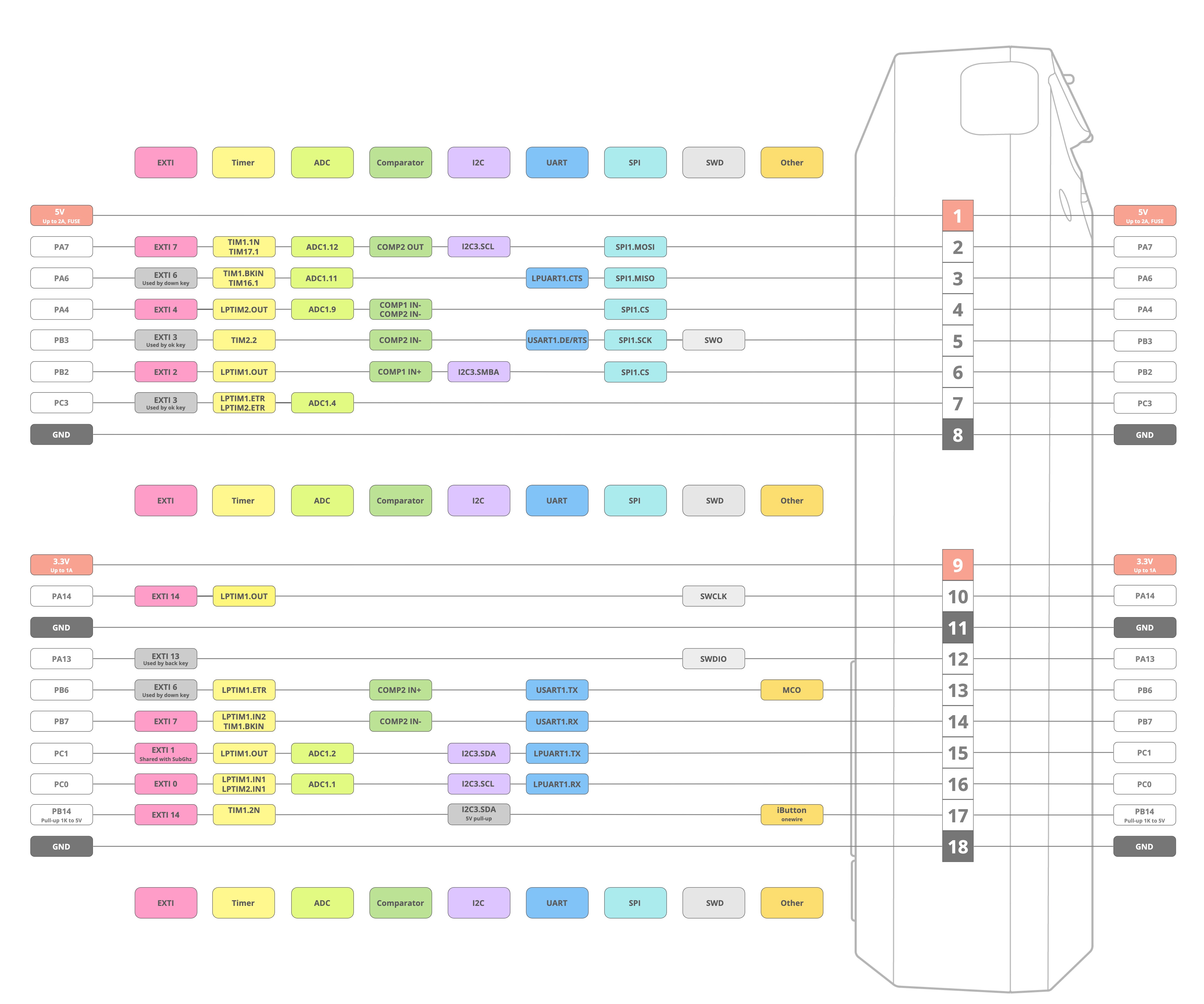
flipper-gpio.jpg | r1 | manage | 745.7 K | 2023-10-28 - 20:21 | PeterSchmid |
This topic: MecrispCube > WebHome > MecrispCubeFlipper > BoardSupportPackageFlipper
Topic revision: r2 - 2023-10-29 - PeterSchmid
Ideas, requests, problems regarding TWiki? Send feedback